OEM Applications Before Selecting Acoustical Materials
- Identify noise source components and where possible determine the relative overall dB levels and frequency distribution.
- Relocate or remove noisy components away from operator areas.
- In air flow systems utilize proper aerodynamic principles to minimize noise generated by turbulence.
- Reduce operating speeds of rotating components.
- Alter operating speeds to avoid coincidence with equipment resonant frequencies.
- Isolate and decouple rotating components from the supporting structure.
- Utilize flexible connections on all equipment intakes, exhaust lines, electrical conduit and other service or utility lines.
- Where practical, manufacture OEM component parts where impingement or impact takes place out of plastics or other non-metallic materials with better inherent damping qualities. Examples include gears, rollers, stops and guides.
- Minimize the use of thin gauge sheet metal for large surface area equipment panels and as necessary use stiffeners and bracing to limit structural resonance that generates airborne noise.
- Minimize the percentage of open area in panels designed to contain noise.
- Utilize closed cell gasketing and seals around doors and removable panel sections.
- Reduce drop heights on parts or material impacting hoppers, chutes and parts bins.
- Where practical, utilize expanded metal instead of sheet metal for belt guards.
| Product Cross Sectional View |
Component Layers |
Recommended Uses |
 |
Adhesive Absorber Facing |
Used to line the inside of cabinets, compartments and panels where the existing skin provides the necessary transmission loss. Increasing the thickness and/or density increases low frequency acoustical absorption. |
 |
Adhesive Damping Absorber Facing |
Used to line the inside of cabinets, compartments and panels where it is necessary to add mass to the existing skin, reduce structural resonance and absorb airborne sound. The absorber layer faces the noise source. |
 |
Adhesive Absorber Barrier |
Used to line the outside surfaces of equipment housings, connected ducts, pipes and other guards and panels where inside surfaces are not practical to treat. The absorber layer acts as a decoupler/spacer to enhance the transmission loss of the barrier. |
 |
Adhesive Absorber Barrier Absorber Facing |
Used to line the inside of cabinets, compartments and panels where the existing skin is light gauge and not capable of providing enough transmission loss. To get the full benefit from these decoupled absorber/barrier composites the percentage of open area in the cabinet or panel should be 10% or less of the total surface area. |
 |
Adhesive Damping |
Used to line inside or outside surfaces of thin metal or other rigid surfaces to reduce noise generated by structural resonance. This product group can be applied in sheets or using a liquid damping compound. |
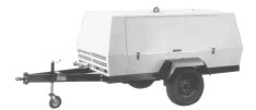 |
Typical source control treatment at left. QWYATTCORE acoustical materials are used to line OEM portable air compressor housings. | |
Fire Safety
The most commonly utilized acoustical foams for OEM applications are polyester and polyether polyurethane materials rated at UL94-HF1. These materials will burn in the presence of a flame and give off toxic combustion products. Although the UL94 rating carries a "self-extinguishing" designation, this terminology is not intended to reflect properties of the material under actual fire conditions. Many of the fiberglass based products and quilted blankets carry class A ratings as per the stringent ASTM E-84 tunnel test. The E-84 class A rating conforms to most fire hazard building code regulations. Some specialty foams have been developed to meet this class A rating.
Density
Performance of absorber products is directly related to the density. In many cases increased density for a given thickness results in increased absorption ratings most dramatically in the low frequency range and reduced performance in the high frequencies. This begins when the absorber product becomes so dense that it begins to take on characteristics of a barrier thus reflecting some of the short wavelength high frequency noise. Density of damping treatments does not usually have a well defined effect on performance although adding more mass to the surface will ultimately change its natural frequency. In barrier materials, doubling the density of the barrier increases the transmission loss by 6dB.
Thickness
Material thickness of absorber products has much the same effect as increasing product density with increased performance in the lower frequencies. Degradation of higher frequency absorption with increased thickness is not typical. Increasing absorber thickness yields a small incremental increase in absorption in high frequencies compared to the increase in low frequencies. In damping materials, thickness of the coverage as it relates to the treated surface thickness will affect performance. As a general rule the damping material should be at least equal to the thickness of the surface it is applied to and two or three times if high loss factors need to be attained. In barrier materials, increasing the thickness changes performance as defined by the mass law which states that transmission loss will increase by 6dB for each doubling of the mass or frequency.
Coverage
Performance of absorber products is not coverage dependent. The function of the absorber materials is to dissipate acoustic energy and limit reverberant build-up. As a general rule 75% of the noise build-up can be eliminated inside an enclosure or compartment with as little as 50% coverage of inside reflective surfaces. Likewise, damping treatments and coatings are not coverage dependent. Attacking surface areas where vibrational motion is most prevalent is more important than 100% coverage. A40% to 60% coverage is usually sufficient. To the contrary barrier materials rely on complete coverage as close to 100% as possible to realize their full acoustic performance. Potential practical limitations for various coverages are as follows: maximum 10dB reduction for 90% coverage, 15dB reduction for 98% coverage and 20dB reduction for 99% coverage.
Facings
Usually it is necessary to incorporate some type of thin membrane facing to cover the absorber layer exposed to the noise source inside a cabinet or enclosure. This protects the product from contamination and provides a surface that can be wiped down. As long as the film facing is in the 1 to 4 mil thickness range there will be a minimal effect on acoustic performance. Many times there is only a frequency shift with slightly lower absorption in higher frequencies and slightly higher absorption in lower frequencies. Damping and barrier materials are many times part of composite products not exposed to the environment and are not covered with facings. Some typical facings are Tedlar, mylar and urethane.
Installation
Most products are available in standard rolls, sheets or die cut to meet OEM specifications. The products can usually be hand cut using a utility knife, scissors, band saw or other common cutting tools. Attachment is recommended with solvent based contact adhesives for the urethane foam absorbers and composites. Adhesive recommendations should be reviewed in detail at the time of application as special considerations must be made depending on the surface shape and preparation, whether the surface is oriented horizontal or vertical and what working time is required. Pressure sensitive adhesive systems (PSA) are available for most products and are highly recommended. High tack acrylic based PSA backings are preferred to assure the best bond. Stick clips, insulation pins and other mechanical fasteners may be necessary in addition to the adhesives.
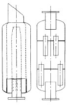 |
Sizing Machinery MufflersMany OEM process systems utilize rotary-positive blowers that will require mufflers or silencers on both the intake and discharge. Without such treatment noise levels could easily be in the 110 to 115dBA range. Blower sizes are described in inches (for example 12x25) where the first number represents the timing gear diameter and the second number represents the length of the rotor. The product of the gear circumference in feet and the blower RPM is the peripheral velocity of the timing gear. Noise and pulsation produced by rotary-positive blowers inherently reaches a critical level at gear pitch-line velocities of about 3300 feet per minute (FPM) for intakes and 2700 FPM for discharges. These critical gear pitch-line velocities are commonly referred to as the blower transition speeds. Muffler selections shown in the QWYATT FLOW muffler product section (page 154) make reference to the blower transition speed. Consult QWYATT Sales Engineers on muffler applications for process systems and for other equipment such as compressors, engines, generators, turbines, etc... |
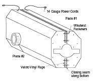
Designing Sound BlanketsCustom fit removable thermal/acoustic blankets such as the one shown at right are designed based on the equipment or component field measurements and/or housing/casing drawings. For proper construction and fit it is necessary to determine the equipment casing surface temperature. The inner and outer jacketing should be completely water resistant and suitable for both caustic and acidic environments. For durability, all blanket construction should be double sewn lock stitch with a minimum of 7 stitches per inch. All mating match seam blankets should have an overlapping flap cover which is also an extension of the loaded vinyl flexible sound barrier layer (internal to the blanket). This is essential for minimizing noise leaks. Stainless steel quilting pins should be utilized no greater than 18" apart to prevent shifting of the insulation. Hog ring construction should be avoided wherever possible in order to assure the highest blanket design quality possible. |
 |
Selecting Ventilation Silencers
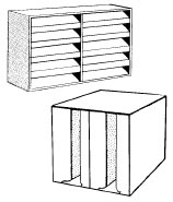 |
Fan and HVAC silencers are commonly used on low pressure air handling systems and equipment. Acoustic louvers are utilized in conjunction with enclosure or mechanical room ventilation where noise isolation is important. The fundamental tone or frequency that a fan produces is a function of each blade on the fan wheel passing the cut-off sheet on the fan housing. This is commonly referred to as the blade passage frequency (BPF). The first and second multiples of the BPF (harmonics) are prominent but less critical. Calculating the BPF is done by multiplying the fan RPM times the number of blades on the fan wheel, divided by 60 (converts to cycles per second or Hertz). Silencer performance can be approximated by finding the rated insertion loss of the silencer in the octave band where the BPF falls. |
Designing Acoustical Enclosures
Noisy equipment and systems may require path control modular acoustical enclosures where source treatments are not practical or effective. Sound enclosures can be freestanding structures, partially integrated or fully integrated with the equipment. Key design considerations for OEM acoustical enclosures include durability, aesthetic appeal, accessibility and visibility, acoustic performance, cost of installation and material manufacturing costs. Depending on the type of equipment, system or process; lighting and ventilation are also important considerations. The goal of the product engineer is to meet the acoustic requirements with a design that incorporates all the necessary features.
| Enclosure Design Rule #1: Air Leaks
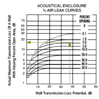
The chart at right shows how actual sound transmission loss relates to the enclosure wall transmission loss potential (from lab test data) and the percent open area. As shown in the example, as little as 2% open area over the entire surface area of an enclosure reduces the 38dB potential transmission loss to only 18dB actual transmission loss. Air leaks occur around windows and doors, at panel joints, around cutouts to accommodate pipes, ducts, utility lines and other obstructions and where the enclosure does not seal against the floor. Where enclosure ventilation is required, openings that are not acoustically baffled will further reduce the actual dB transmission loss. |
 |
Effective Enclosure Design Will Assure
the Lowest $ per dB Cost
Enclosure Design Rule #2: Ventilation
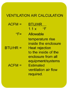 |
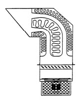
Heat build-up inside acoustical enclosures can be dissipated using forced ventilation fans and blowers in a draw through (see right) or blow through design. The intake and discharge of forced ventilation systems must be acoustically treated with louvers, lined baffles, hoods or duct silencers. The owner or designer of the enclosed equipment needs to determine what is sufficient air flow to dissipate heat. The formula at left is a good guideline. Proper placement and location of intake and discharge openings should ideally bring in air low on one side or end of the enclosure and draw air over the equipment before exiting high on the opposite end or side. |
 |
Enclosure Design Rule #3: Access
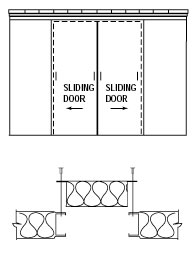 |
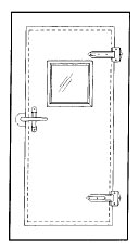
Removable panel sections (bottom left) can allow for infrequent maintenance access in a limited area. Hinged doors (at right) provide for more frequent access but require clearance for the door swing outside the enclosure. Sliding doors (see left) also provide easy access without protruding into work area space outside the enclosure. Acoustical performance of sliding doors is less than that of hinged doors. Double doors provide access to a larger area. Sliding or removable roof panels and sections are best for major repairs requiring a crane. Small enclosure designs can be a knock down design where all panels are latched together for quick and easy disassembly. |
 |
Far Field
The far field describes a sound field beyond the near field limits described above where the sound pressure level (SPL) drops off at the theoretical rate of 6dB for every doubling of distance from the source. This rule of thumb is called the Inverse Square Law. Please note that if the far field does not meet the criteria for a free field as described below, then less than the theoretical drop rate will pertain. In such case doubling the distance from the source may yield a drop rate of 3-4dB.Free
FieldTo be considered free field there can be no obstructing surfaces in the sound path of spherical wave propagation. Free field conditions are characterized by SPL loss rates following the Inverse Square Law. Free field references pertain to large open outdoor spaces or in rooms where walls and other surfaces are almost completely absorptive. Anechoic (without echoes) acoustical test chambers simulate free field conditions where omnidirectional sound wave propagation exists.Direct
FieldThe direct sound field is also used to describe far field conditions that follow the Inverse Square Law SPL loss rate of 6dB for every doubling of the distance. The actual formula used to make calculations at various distances in the far/direct field is as follows: SPL1 [20x log (d2/d1)] = SPL2 where SPL1 is the noise level at the location closer to the source at a distance of d1 from the source and SPL2 is the noise level at a location farther from the source at a distance of d2.Diffuse
FieldIn a diffuse field there are so many reflections contributing to the total sound field that sound levels measured virtually anywhere in the sound field are the same. Diffuse fields usually pertain to indoor environments. Rooms that are categorized as "live" have larger diffuse fields than free fields. "Dead" rooms have much larger free fields than diffuse fields.Reverberant
FieldThe reverberant field is essentially the same as the diffuse field. For indoor sound field discussions it is used to contrast direct fields. Reverberation test chambers have all room surfaces almost completely reflective so that total sound energy remains constant throughout the environment and sound levels can be measured independent of location and distance.
| Near Field | The near field is the region close to a sound source usually defined as 1/4 of the longest wavelength of the source. Near field noise levels are characterized by drastic fluctuations in levels as much as 10dBA for small changes in distance from the source. Near field references can pertain to both indoor and outdoor environments. |
Please refer to the figure below which shows the relationship between sound fields.
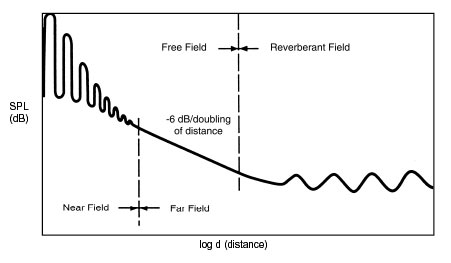
Sound Fields Relative To Distances From A Source

